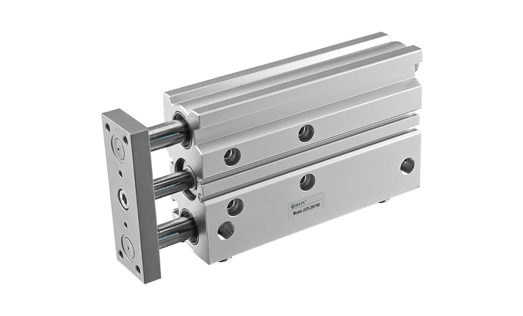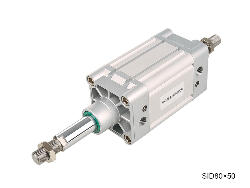

Besonderheit:
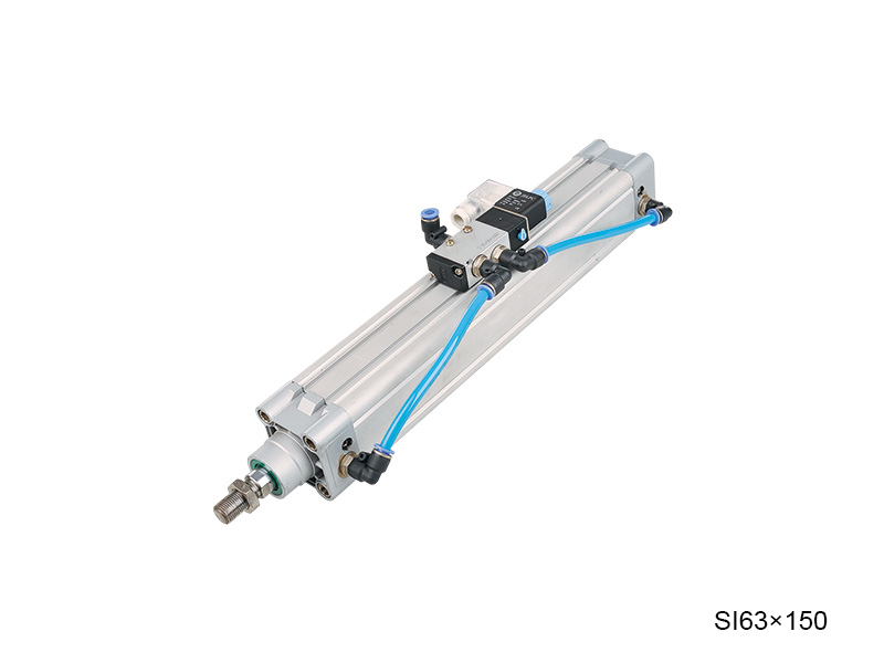
1. Der Zylinder entspricht dem LSO15552
2. Die Kolbendichtung verwendet zwei NBR-PA-Material als Einweg-Versiegelungsstruktur vom Typ y mit Kompensationsfunktion, langer Lebensdauer und niedrigem Startdruck.
3. Die Stabdichtung verwendet Pu -Material mit den Eigenschaften hoher Festigkeit, guter Zähigkeit, Verschleißfestigkeit. Ölfestigkeit und Alterungsbeständigkeit.
4.. Das Kolbenstangestangenmaterial wird mit 45 ° C -Kohlenstoffstahl mit harter Chrombeschichtung auf der Oberfläche und der Rauheit ra <0,4 hergestellt, mit guter Verschleißfestigkeit und Rostbeständigkeit.
Interne Struktur
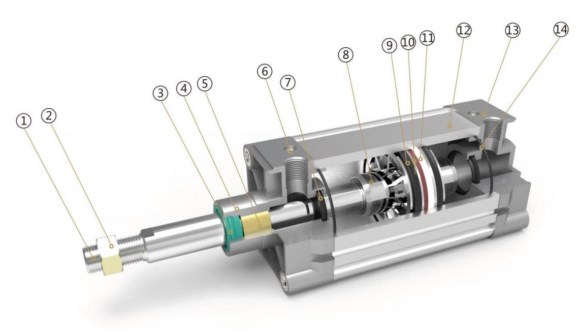
Teile
| Nummer | Name | Nummer | Name |
| 1 | Kolbenstangestange | 8 | Kolbenstange |
| 2 | Sechseckmutter | 9 | Y Ring |
| 3 | Wellenabdichtung | 10 | Magnet |
| 4 | Vorderdeckel | 11 | Reibungsring |
| 5 | Kupferrohr | 12 | Zylinderlaufbuchse |
| 6 | Dämpfungsverstellschraube | 13 | Rückdeckel |
| 7 | Dämpfungsdichtung | 14 | O Ring |
Bestellcode
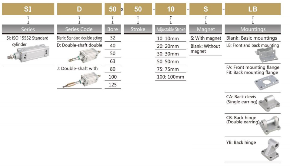
*Sensormodell JEL-30, finden Sie in P173 für den spezifischen Bestellcode.
Spezifikation
| Bohrung (MM) | 32 | 40 | 50 | 63 | 80 | 100 | 125 |
| Betrieb | Doppeltwirkend | ||||||
| Arbeitsmedium | Luft | ||||||
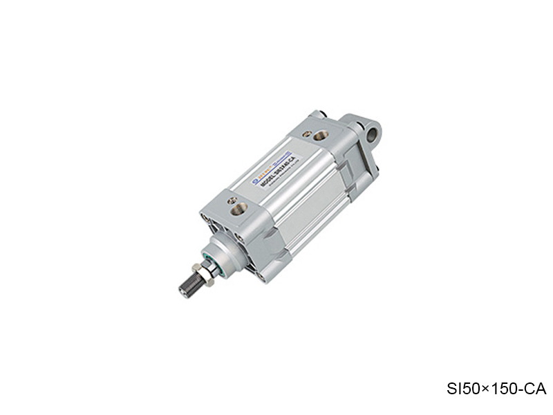
| Montage | Basic fa fb ca cb lb yb | ||||||
| Betriebsdruckbereich | 1 ~ 9,0 kgf/cm² | ||||||
| Beweisdruck | 13,5 kgf/cm² | ||||||
| Betriebstemperaturbereich | -20 ~ 80 ℃ | ||||||
| Betriebsgeschwindigkeitsbereich | 50 ~ 800 mm/s | ||||||
| Dämpfer | Einstellbares Dämpfer | ||||||
| Einstellbarer Dämpferstrich | 20 mm | 26 mm | |||||
| Anschlussterminalgröße | G1/8 " | G1/4 " | G3/8 " | G1/2 ” | |||
Schlaganfall
| Bohrung | Standardschlag | Max.stroke | Zulässiger Schlaganfall |
| 32 | 25 50 75 80 100 125 150 160 175 200 250 300 350 400 450 500 | 1000 | 2000 |
| 40 | 25 50 75 80 100 125 150 160 175 200 250 300 350 400 450 500 600 700 800 | 1200 | 2000 |
| 50 | 25 50 75 80 100 125 150 160 175 200 250 300 350 400 450 500 600 700 800 900 1000 | 1200 | 2000 |
| 63 | 25 50 75 80 100 125 150 160 175 200 250 300 350 400 450 500 600 700 800 900 1000 | 1500 | 2000 |
| 80 | 25 50 75 80 100 125 150 160 175 200 250 300 350 400 450 500 600 700 800 900 1000 | 1500 | 2000 |
| 100 | 25 50 75 80 100 125 150 160 175 200 250 300 350 400 450 500 600 700 800 900 1000 | 1500 | 2000 |
| 125 | 25 50 75 80 100 125 150 160 175 200 250 300 350 400 450 500 600 700 800 900 1000 | 1500 | 2000 |
Gesamtdimension
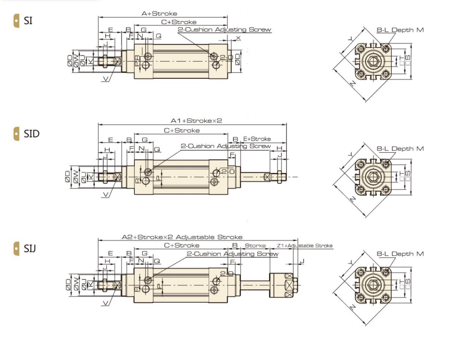
Dimension
| Bohrung/Symbol | A | A1 | A2 | B | C | D | E | F | G | H | I | J | K | L |
| 32 | 143 | 190 | 185 | 16 | 94 | 30 | 33 | 10 | 25 | 22 | 17 | 6 | M10 × 1,25 | M6 |
| 40 | 159 | 213 | 207 | 20 | 105 | 35 | 34 | 10 | 29.5 | 24 | 17 | 7 | M12X1.25 | M6 |
| 50 | 175 | 244 | 233 | 27 | 107 | 40 | 42 | 10 | 32 | 32 | 23 | 8 | M16X1.5 | M8 |
| 63 | 190 | 258 | 247 | 26 | 122 | 45 | 42 | 10 | 36 | 32 | 23 | 8 | M16X1.5 | M8 |
| 80 | 214 | 301 | 288 | 35 | 126 | 45 | 53 | 10 | 37 | 40 | 26 | 10 | M20 × 1,5 | M10 |
| 100 | 229 | 321 | 308 | 40 | 137 | 55 | 52 | 10 | 39 | 40 | 26 | 10 | M20X1.5 | M10 |
| 125 | 279 | 394 | 378 | 47 | 160 | 60 | 72 | 10 | 43 | 54 | 40 | 12 | M27X2 | M12 |
| Bohrung/ Symbol | M | N | O | P | Q | R | S | T | U | V | W | X | Y | Z | Z1 |
| 32 | 12 | 15 | G1/8 | 5 | 3 | 6.5 | 45 | 32.5 | 12 | 10 | 28 | 4 | 46 | 58.7 | 21 |
| 40 | 12 | 17.5 | G1/4 | 7 | 3 | 7 | 52 | 38 | 16 | 13 | 33 | 4 | 53.7 | 68 | 21 |
| 50 | 12 | 20 | G1/4 | 7 | 3 | 9 | 65 | 46.5 | 20 | 17 | 38 | 4 | 65.8 | 84.5 | 23 |
| 63 | 12 | 22 | G3/8 | 8 | 5 | 9 | 76 | 56.5 | 20 | 17 | 38 | 4 | 79.9 | 99.6 | 23 |
| 80 | 15 | 23 | G3/8 | 10 | 5 | 12 | 94 | 72 | 25 | 22 | 43.5 | 4 | 101.8 | 123.8 | 29 |
| 100 | 15 | 26 | G1/2 | 10 | 5 | 14 | 112 | 89 | 25 | 22 | 47 | 4 | 125.9 | 148.9 | 29 |
| 125 | 20 | 29 | G1/2 | 10 | 5 | 14 | 134 | 110 | 32 | 27 | 53 | 6 | 156.9 | 179.6 | 40.5 |
LB Fuß Gesamtdimension
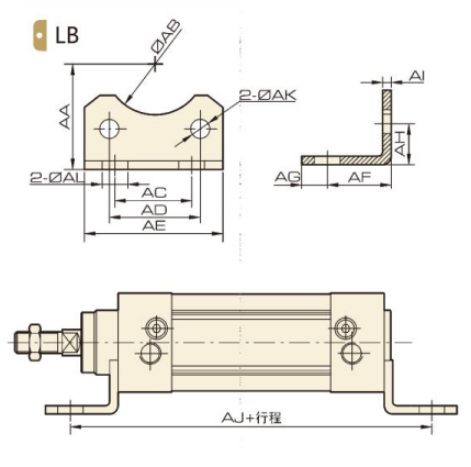
Dimension
| Bohrung/Symbol | 32 | 40 | 50 | 63 | 80 | 100 | 125 |
| AA | 32 | 36 | 45 | 50 | 63 | 71 | 90 |
| AB | 30 | 35 | 40 | 45 | 45 | 55 | 60 |
| AC | 32 | 36 | 45 | 50 | 63 | 75 | 90 |
| AD | 32.5 | 38 | 46.5 | 56.5 | 72 | 89 | 110 |
| AE | 45 | 52 | 65 | 75 | 95 | 115 | 140 |
| AF | 24 | 28 | 32 | 32 | 41 | 41 | 45 |
| AG | 11 | 8 | 15 | 13 | 14 | 16 | 18 |
| AH | 15.8 | 17 | 21.8 | 21.8 | 27 | 26.5 | 35 |
| AI | 4 | 4 | 5 | 5 | 6 | 6 | 7 |
| AJ | 142 | 161 | 170 | 186 | 208 | 219 | 250 |
| AK | 7 | 7 | 9 | 9 | 11 | 11 | 12.5 |
| AL | 7 | 10 | 10 | 10 | 12 | 14.5 | 16.5 |
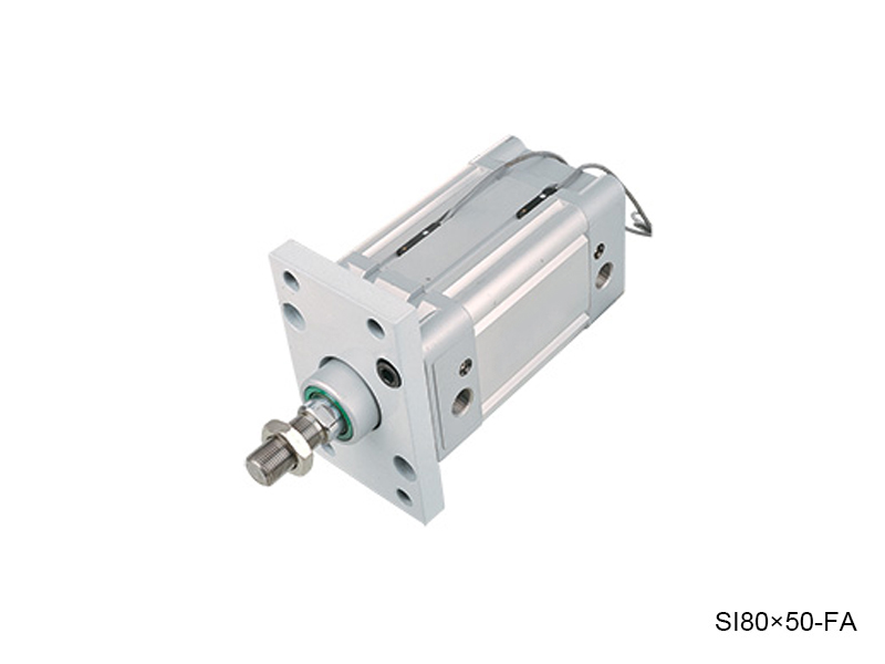
FA / FB Flansch Gesamtdimension
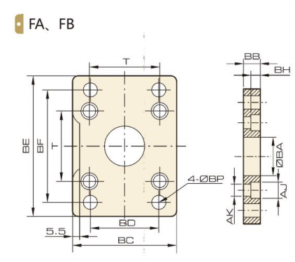
Dimension
| Bohrung/Symbol | 32 | 40 | 50 | 63 | 80 | 100 | 125 |
| BB | 30.3 | 35.3 | 40.3 | 45.3 | 45.3 | 55.3 | 60.3 |
| BB | 10 | 10 | 12 | 12 | 16 | 16 | 20 |
| BC | 45 | 52 | 65 | 76 | 94 | 112 | 140 |
| BD | 32 | 36 | 45 | 50 | 63 | 75 | 90 |
| BE | 80 | 90 | 110 | 120 | 150 | 175 | 224 |
| BF | 64 | 72 | 90 | 100 | 126 | 150 | 180 |
| BH | 6.5 | 6.5 | 8.5 | 8.5 | 10.5 | 10.5 | 15 |
| AJ | 10.5 | 10.5 | 13.5 | 13.5 | 16.5 | 16.5 | 19 |
| AK | 6.5 | 6.5 | 8.5 | 8.5 | 10.5 | 10.5 | 12.5 |
| BP | 7 | 9 | 9 | 9 | 12 | 14 | 16 |
| T | 32.5 | 38 | 46.5 | 56.5 | 72 | 89 | 110 |
Ca Scharnier Gesamtdimension
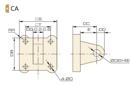
Dimension
| Bohrung/Symbol | 32 | 40 | 50 | 63 | 80 | 100 | 125 |
| S | 45 | 52 | 65 | 76 | 94 | 112 | 140 |
| T | 32.5 | 38 | 46.5 | 56.5 | 72 | 89 | 110 |
| RR | 6.5 | 6.5 | 9 | 9.5 | 11 | 11.5 | 12 |
| DB | 34 | 41 | 54 | 65 | 83 | 101 | 123 |
| DC | 22 | 25 | 27 | 32 | 36 | 41 | 50 |
| DD | 10 | 11 | 13 | 16 | 16 | 20 | 25 |
| DE | 10 | 12 | 12 | 16 | 16 | 20 | 25 |
| DQ | 26 | 28 | 32 | 40 | 50 | 60 | 70 |
| D | 6.5 | 6.5 | 8.5 | 8.5 | 10.5 | 10.5 | 12.5 |
| E | 14 | 17 | 17 | 22 | 24 | 25 | 30 |
CB -Scharnier Gesamtdimension
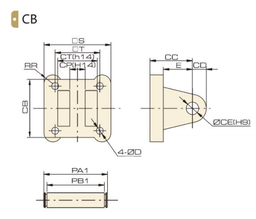
Dimension
| Bohrung/Symbol | 32 | 40 | 50 | 63 | 80 | 100 | 125 |
| S | 45 | 52 | 65 | 76 | 94 | 112 | 140 |
| T | 32.5 | 38 | 46.5 | 56.5 | 72 | 89 | 110 |
| D | 6.5 | 6.5 | 8.5 | 8.5 | 10.5 | 10.5 | 12.5 |
| E | 14 | 17 | 17 | 22 | 24 | 25 | 30 |
| RR | 6.5 | 6.5 | 9 | 9.5 | 11 | 11.5 | 12 |
| CB | 34 | 41 | 54 | 65 | 83 | 101 | 123 |
| CC | 22 | 25 | 27 | 32 | 36 | 41 | 50 |
| CD | 10 | 11 | 13 | 16 | 46 | 20 | 25 |
| CE | 10 | 12 | 12 | 16 | 16 | 20 | 25 |
| CP | 26 | 28 | 32 | 40 | 50 | 60 | 70 |
| CT | 45 | 52 | 60 | 70 | 90 | 110 | 120 |
| PA1 | 53 | 60 | 68 | 78 | 100 | 120 | 130 |
| PB1 | 46.5 | 53.5 | 61.5 | 71.5 | 91.5 | 111.5 | 121.5 |
Yb Scharnier Gesamtdimension
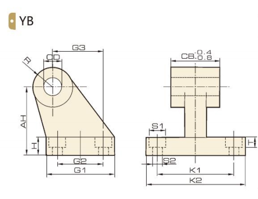
Dimension
| Bohrung/Symbol | 32 | 40 | 50 | 63 | 80 | 100 |
| AH | 32 | 36 | 45 | 50 | 63 | 71 |
| H | 8 | 10 | 12 | 12 | 14 | 15 |
| CD | 10 | 12 | 12 | 16 | 16 | 20 |
| G1 | 31 | 35 | 45 | 50 | 60 | 70 |
| G2 | 18 | 22 | 30 | 35 | 40 | 50 |
| G3 | 21 | 24 | 33 | 37 | 47 | 55 |
| CB | 26 | 28 | 32 | 40 | 50 | 60 |
| K1 | 38 | 41 | 50 | 52 | 66 | 76 |
| K2 | 51 | 54 | 65 | 67 | 86 | 96 |
| S2 | 6.6 | 6.6 | 9 | 9 | 11 | 11 |
| R | 10 | 11 | 13 | 15 | 15 | 19 |
Nr. 1 Xingjia Straße, Pneumatischer Industriepark, Ortschaft Xikou, Ningbo, Provinz Zhejiang, 315502
+86-574-88869818
+86-574-88869826
+86-574-88869817
+86-574-88869816
+86-574-88869833
royshan@jelpc.com
Copyright Ningbo Jiaerling Pneumatic Machinery Co.,Ltd.. Alle Rechte vorbehalten. 
China Proportionalventile Hersteller
 简体中文
简体中文 English
 日本語
日本語 한국어
한국어 Deutsch